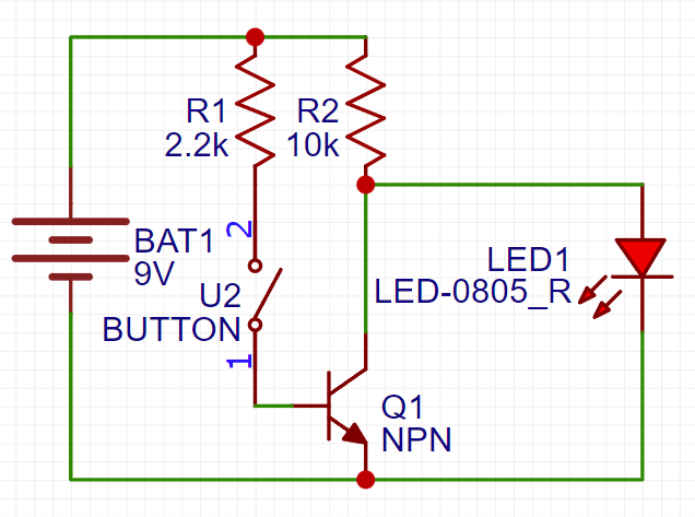
NPN Inverter Schematic

In this simple inverter circuit, when the button is not pressed, the current takes the only path that it has which is from the cathode of the 9V battery, through the LED,(lighting it up), and then back into the anode. However, when the button is pressed, a little bit of the current from the battery flows into the base pin of the NPN transistor, activating it, and allowing for the flow of current through the transistor instead, from the collector to the emitter pin. Because this is the path of least resistance, the current flows this way and therefore no longer goes through the LED, which turns it off. When the button is pressed, the LED is off, and when it is not pressed, the LED is on.