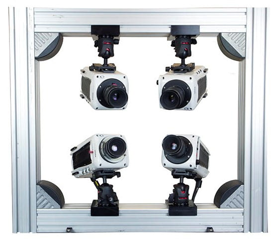
We have the following experimental apparatus available for student and industry research.
Kirsten Wind Tunnel
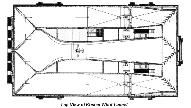
Closed loop, 8 X 10 ft, capable of wind speeds up to 200mph.
Visit KWT webpage.
3′ x 3′ Wind Tunnel
Open loop, 3 X 3 X 8 ft, capable of wind speeds up to 125 mph.
Visit 3′ x 3′ webpage.

Air-Sea Tunnel
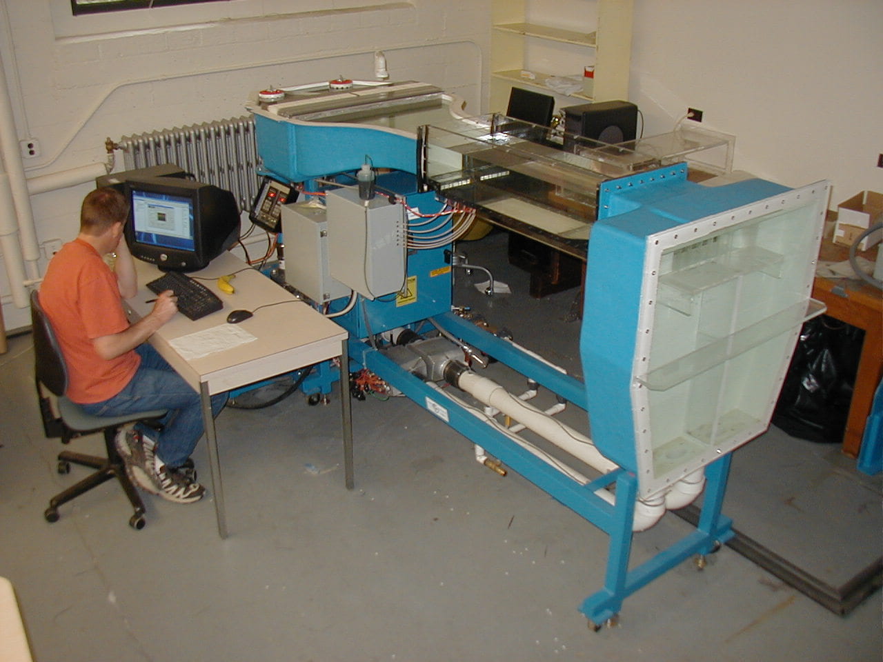
The Air-Sea tunnel is a laboratory testing tank designed to investigate wind-wave-current interactions, though it can be run as a channel flow facility. The facility consists of an 12.2 m (40’) long test section with glass along the entire length of one side. The cross-section is 1.2 m high x 0.9 m wide and is filled to a water depth of 0.76 m. The head space above for air flow measures 0.45 m. The maximum wind speed is 10 m s-1 and the maximum water current in both directions is 0.30 m s-1 with the full working depth and 0.51 m s-1 with a working depth of 0.45 m using a false bottom. The water current is generated by a centrifugal pump rated at 100 gal/s via the facility’s 16 inch return flow pipe.

6″ X 12″ Shear Tunnel
The shear tunnel water facility is an unpressurized, closed circuit arranged with the flow loop in a vertical configuration. The test section, 6″x12″x36″, may be operated with a free water surface. The flow velocity in the test section varies continuously from 0.1 fps (0.03 m/s) to 3.28 fps (1.0 m/s). The shear tunnel contains a removable splitter plate that can be vertically mounted within the centerline of the test section.
Micro-scale 2D/3D PIV/PTV
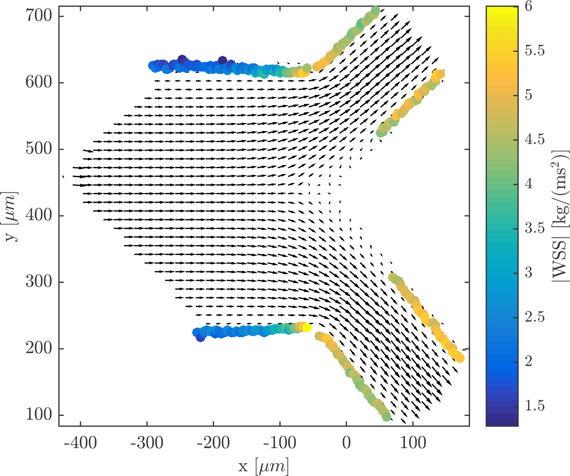
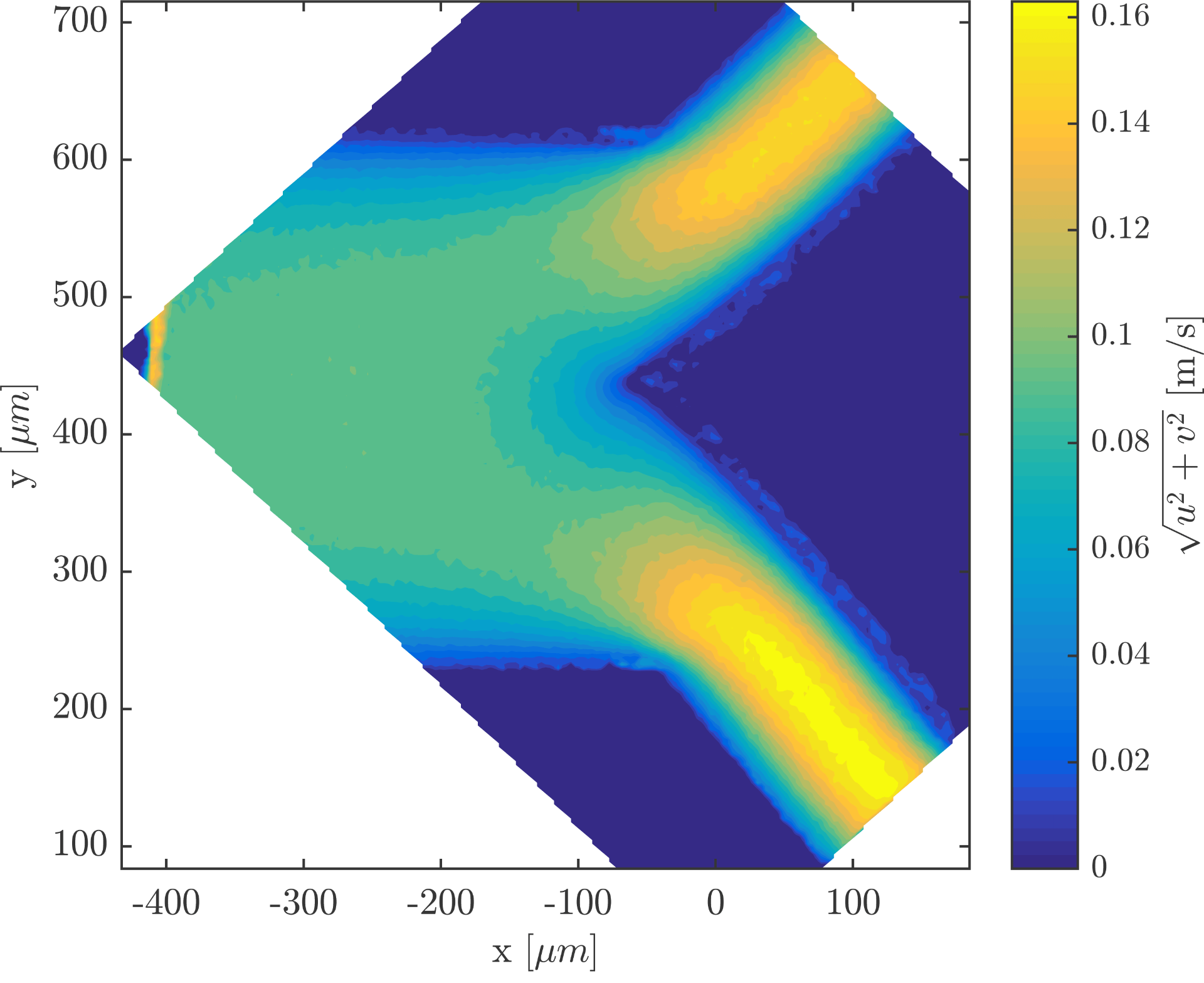
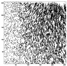
We have innovated on algorithms to extract wall shear stress for microscopic flows. Below, the flow field at the central measurement plane of a bifurcation (left) shows the vector field with the calculated WSS at the calculated wall positions. For clarity, only every fifth vector in both directions is plotted. On the right is the absolute velocity.
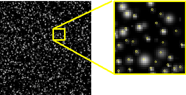
Our algorithmic innovations have allows us to accurately track particle velocities in 2D at seeding concentrations as high as 0.1 ppp.
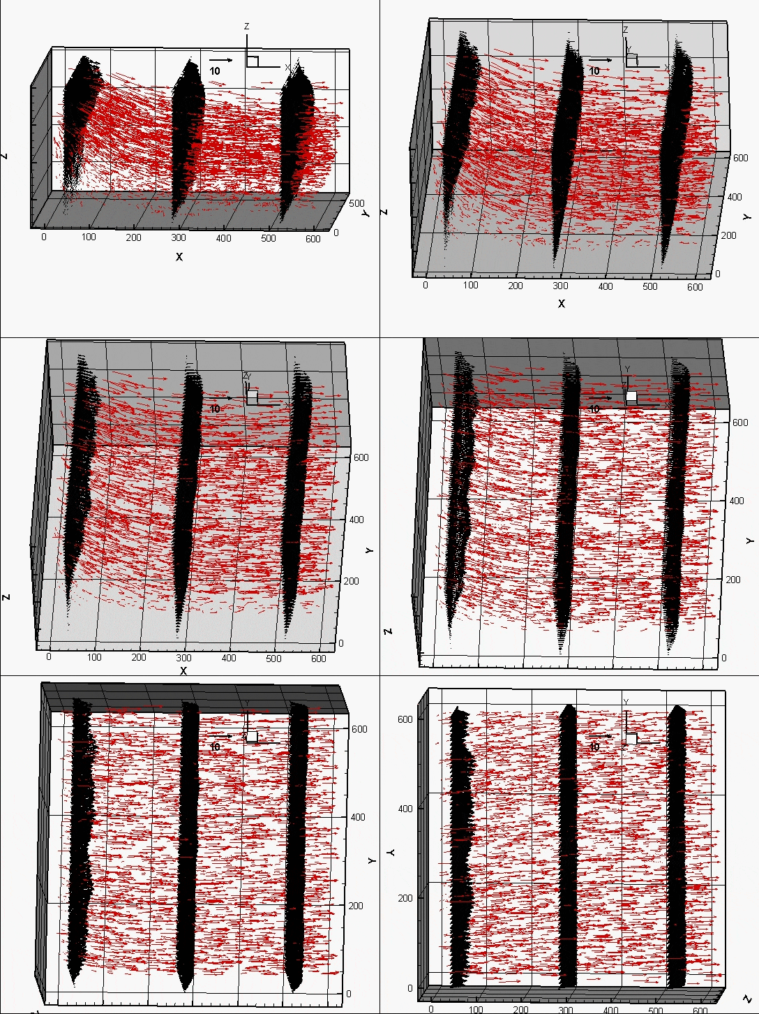
We have also extended the2D PTV algorithms to 3D PTV and have used it to measure flow over a micro-backward-facing step (below left). The channel dimension is 22 mm × 6 mm × 0.35 mm before the step and 15 mm × 6mm × 0.6 mm after the step. The laminar flow is driven by a syringe pump (NewEra NE-1000), and deionized (DI) water is used as the working fluid. 2 μm polystyrene particles (Polybead® Microspheres, Polysciences Inc.) are used as the tracer particles. Units shown are in um. We have also used it to image flow with a 2840 Hz oscillatory component through a micro-pillar array (below right).
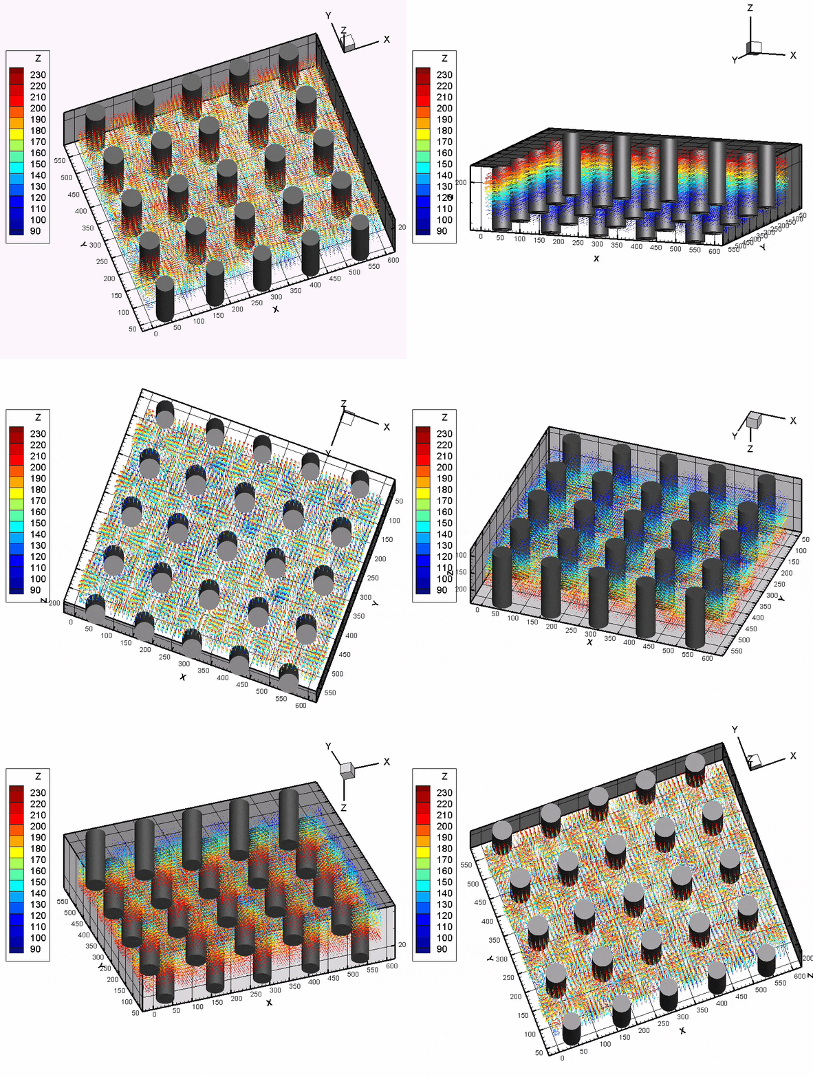
High-Speed Imaging System for Flow Visualization or 2D/3D PIV/PTV
We have several high-speed imaging cameras/data acquisition systems that allow us to study fast-evolving time flow, either in 2D or 3D.
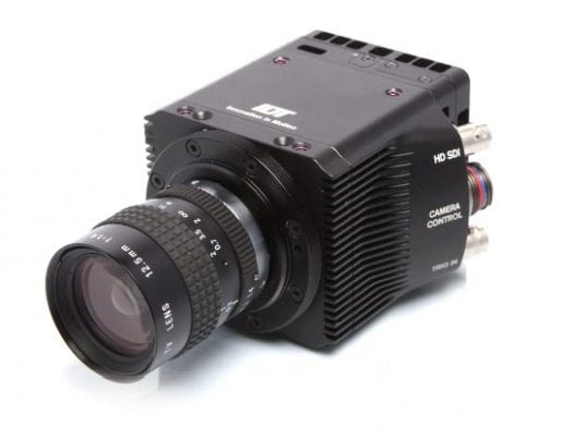
Image by IDT Vision.


